- 您现在的位置:买卖IC网 > Sheet目录322 > DS28DG02E-3C+T (Maxim Integrated)IC EEPROM 2KBIT 2MHZ 28TSSOP
DS28DG02: 2Kb SPI EEPROM with PIO, RTC, Reset, Battery Monitor, and Watchdog
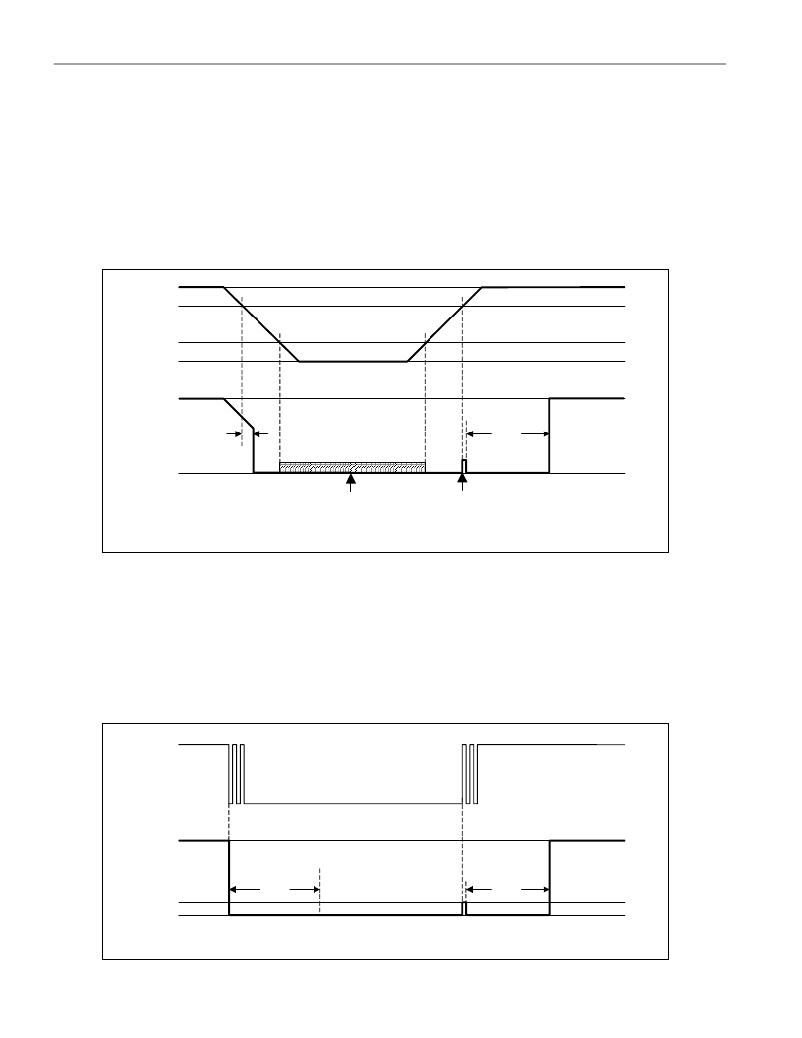
MONITORING FUNCTIONS
The DS28DG02 has two voltage monitors: one for the V CC supply voltage and another one for the battery that
supplies the RTC and associated registers if V CC is switched off. If V CC falls below the V TRIP threshold the V CC
monitor activates the open-drain RSTZ output, as shown in Figure 6. There is a delay of t DEL between crossing the
trip point and RSTZ going LOW. As long as V CC is above V POR or the device has a functioning battery backup, the
logic level at RSTZ does not exceed V OLmax . Without battery support, the state of the RSTZ output is undefined for
V CC values below V POR . When V CC ramps up, RSTZ remains at LOW until the V TRIP threshold is reached. As V TRIP is
crossed, the voltage at RSTZ rises until it reaches V TRMS , the manual reset release threshold. This activates the
debounce circuit, which holds RSTZ low for t RST . After t RST is expired, the voltage at RSTZ ramps up to the value of
the applied pullup voltage.
Figure 6. RSTZ Power-Fail Reset
V CC
V TRIP
V POR
V CC
*
RSTZ
t DEL
t RST
V CC or the applicable pullup voltage for the RSTZ pin.
With the V BAT pin tied to V CC , the RSTZ behavior for
V CC < V POR is undefined.
*
As V TRIP is crossed, the voltage at
RSTZ starts rising, which triggers
the manual switch debounce
circuit and activates RSTZ for t RST .
The RSTZ pin is internally connected to a debounce circuit, which allows using a manually operated switch to
generate a reset signal. Figure 7 illustrates the timing of the manual reset. As the switch closes, it forces the
voltage at RSTZ to fall below V ILmax , which triggers the debounce circuit. Now the voltage at RSTZ is held at logic
LOW by both, the manual switch and the debounce circuit. When the manual switch is opened or t DEB is over,
(whichever occurs later) the voltage at RSTZ rises until it reaches V TRMS . This again triggers the debounce circuit,
which holds RSTZ low for t RST , after which the voltage at RSTZ ramps up to the pullup voltage. The minimum LOW
time of a manually generated reset is t DEB + t RST .
Figure 7. RSTZ Manual Switch Debounce
Open
Manual
Switch
closed
V CC
*
RSTZ
V TRMS
RSTZ held low by
DS28DG02
t DEB
RSTZ held low
by manual switch
t RST
V CC or the applicable pullup voltage for the RSTZ pin.
For t RST to start, the voltage at RSTZ has to cross V TRMS after t DEB is expired.
*
15 of 34
发布紧急采购,3分钟左右您将得到回复。
相关PDF资料
DS28E04S-100+T
IC EEPROM 4KBIT 16SOIC
DS28EC20+T
IC EEPROM 20KBIT TO92-3
DS301X
KWIK-CHG DESIGNATION STRIP SGL
DS3030W-100#
IC NVSRAM 256KBIT 100NS 256BGA
DS3045W-100#
IC NVSRAM 1MBIT 100NS 256BGA
DS3050W-100#
IC NVSRAM 4MBIT 100NS 256BGA
DS3065W-100#
IC NVSRAM 8MBIT 100NS 256BGA
DS3065WP-100IND+
IC SRAM 3.3V 8MB 34POWERCAP MOD
相关代理商/技术参数
DS28DG02EVKIT
功能描述:存储器 IC 开发工具 RoHS:否 制造商:STMicroelectronics 产品:Reference Boards 工具用于评估:M24LR64-R 存储容量:64 kbit 存储类型:EEPROM 工作电源电压:1.8 V to 5.5 V
DS28DG02G-3C+
功能描述:电可擦除可编程只读存储器 2Kb SPI 电可擦除可编程只读存储器 w/PIO RTC/Rst/Bat Mtr/Wtdg RoHS:否 制造商:Atmel 存储容量:2 Kbit 组织:256 B x 8 数据保留:100 yr 最大时钟频率:1000 KHz 最大工作电流:6 uA 工作电源电压:1.7 V to 5.5 V 最大工作温度:+ 85 C 安装风格:SMD/SMT 封装 / 箱体:SOIC-8
DS28DG02G-3C+T
功能描述:电可擦除可编程只读存储器 2Kb SPI 电可擦除可编程只读存储器 w/PIO RTC/Rst/Bat Mtr/Wtdg RoHS:否 制造商:Atmel 存储容量:2 Kbit 组织:256 B x 8 数据保留:100 yr 最大时钟频率:1000 KHz 最大工作电流:6 uA 工作电源电压:1.7 V to 5.5 V 最大工作温度:+ 85 C 安装风格:SMD/SMT 封装 / 箱体:SOIC-8
DS28E01-100
制造商:MAXIM 制造商全称:Maxim Integrated Products 功能描述:带SHA-1引擎保护的1K位1-Wire EEPROM
DS28E01-100_12
制造商:MAXIM 制造商全称:Maxim Integrated Products 功能描述:1Kb Protected 1-Wire EEPROM with SHA-1 Engine
DS28E01-100+
功能描述:电可擦除可编程只读存储器 RoHS:否 制造商:Atmel 存储容量:2 Kbit 组织:256 B x 8 数据保留:100 yr 最大时钟频率:1000 KHz 最大工作电流:6 uA 工作电源电压:1.7 V to 5.5 V 最大工作温度:+ 85 C 安装风格:SMD/SMT 封装 / 箱体:SOIC-8
DS28E01G-100+R
制造商:DALLAS 制造商全称:Dallas Semiconductor 功能描述:1K-Bit Protected 1-Wire EEPROM with SHA-1 Engine
DS28E01G-100+T
制造商:DALLAS 制造商全称:Dallas Semiconductor 功能描述:1K-Bit Protected 1-Wire EEPROM with SHA-1 Engine
